


i all
details
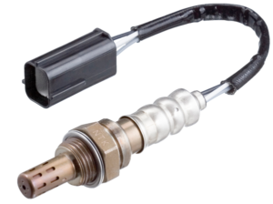
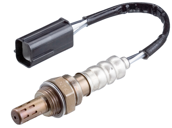
How to Test Oxygen Sensors
For the ECU to control the AFR and keep it within tight limits, the oxygen sensor must be working properly. Failed or worn out oxygen sensors cause problems such as poor fuel economy, failed emission tests, failure of the catalytic converter and poor driveability.
Therefore it is important that you can read the signs of a failed or worn oxygen sensor and have the ability to check their performance.
ON CAR TEST
Before you can test the operation of the sensor, you will need an oscilloscope. You should first check that the basic engine set up is to the manufacturers specification, then thoroughly warm up the engine – remember that the sensor will only function once it has reached its operating temperature.
Using an appropriate connecting device, connect the sensor output to your oscilloscope; do not disconnect the sensor from the ECU. Run the engine at approximately 2000 rpm. A properly functioning oxygen sensor will show a rapidly fluctuating output voltage between approximately 0.1 and 1.0 volts. The time taken for the voltage to change from 0.1 V to 1.0 V (referred to as the lean to rich response time) should be about 300 milliseconds. A similar time should be measured when the voltage changes from 1.0 V to 0.1 V (rich to lean response time).
If the sensor output is constant or the response time is too slow the sensor should be changed. It is a good idea to check the oxygen sensor function at every tune up and before submitting cars for emission tests. A slow sensor will affect fuel economy. A new sensor will pay for itself by cutting fuel costs.